Drive Belt Troy Bilt Bronco Guide: Steps & Parts
When your riding mower starts losing power on slight inclines, hesitates when you press the drive pedal, or gives off a distinct burning rubber scent, the transmission drive system is usually crying out for attention. Diagnosing and replacing the drive belt troy bilt bronco tractors rely on can restore snappy forward and reverse movement without paying shop labor rates. Because Troy-Bilt Bronco mowers feature a specific belt setup beneath the chassis, understanding how the belt routes and functions will save you hours of trial and error.
Understanding the Troy-Bilt Bronco Drive System
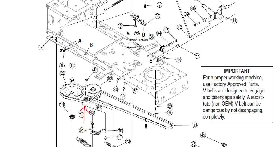
Before ordering parts or unbolting brackets, you must determine which transmission style your Bronco uses. Most traditional Troy-Bilt Bronco models (built on the MTD "F-frame" platform) feature an AutoDrive or CVT (Continuously Variable Transmission) drive system. Unlike simpler single-belt hydrostatic designs, this setup uses two separate drive belts to transfer power from the engine crankshaft back to the rear transaxle:
- The Front / Lower Drive Belt (Engine to Variable Speed Pulley): Runs from the dual stack pulley on the engine crankshaft back to the center variable-speed pulley located beneath the seat area.
- The Rear / Upper Drive Belt (Variable Speed to Transaxle): Connects the center variable-speed pulley to the input pulley atop the rear transmission.
Hydrostatic variants (such as the Bronco Hydro) differ by running a single, longer hydrostatic drive belt directly from the engine pulley to the hydrostatic transaxle. Check your tractor’s model tag beneath the tilting seat before buying to confirm whether you need a dual-belt set or a single hydro belt.
Common OEM Part Numbers for Bronco Drive Belts
Never install standard fractional automotive belts on your lawn tractor. Agricultural and mower drive belts feature aramid or Kevlar cords designed to withstand sudden shock loads and clutching friction without stretching or snapping.
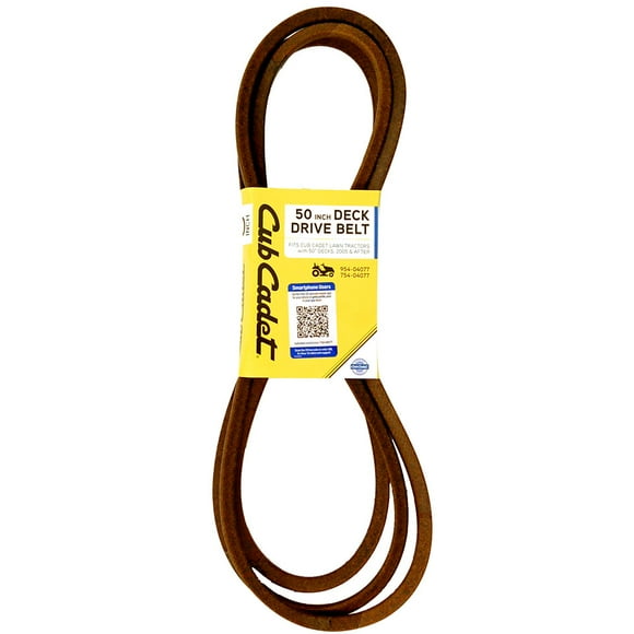
- Front/Lower Drive Belt (CVT Models): OEM part numbers 754-0467A / 954-0467A (typically 5/8-inch wide by ~90.8 inches long).
- Rear/Upper Drive Belt (CVT Models): OEM part numbers 754-0468 / 954-0468 (typically 5/8-inch wide by ~41.5 inches long).
- Hydrostatic Drive Belt (Select Models): OEM part numbers 754-04208 / 954-04208.
Pro tip: If your mower has more than 150 operating hours and you are replacing the lower belt, replace the upper belt simultaneously. Getting access to the drive system requires removing the cutting deck; doing both belts at once prevents having to repeat the disassembly a few weeks later.
Symptoms of a Failing Drive Belt
Drive belts wear down along their angled sidewalls over time. As the belt narrows, it sinks deeper into pulley V-grooves, reducing effective tension. Watch for these telltale signs:
- Loss of Ground Speed: The engine revs cleanly, but the mower crawls sluggishly, especially when cutting heavy grass or traversing hills.
- Jerky Pedal Engagement: The tractor shudders or lurches abruptly when the drive pedal is depressed or released.
- Visible Damage: Deep cracks along the inner ribs, frayed outer fabric cords, or shiny, glazed sidewalls caused by slipping against hot metal pulleys.
- Tractor Fails to Move: If the belt has completely slipped off an idler or snapped, the tractor will not move forward or backward even though the engine runs normally.
Tools and Safety Preparations
Servicing the drive system takes between 60 and 90 minutes. You will need:
- 3/8-inch drive ratchet and socket set (1/2-inch, 9/16-inch, and 7/16-inch are common)
- Belt hook tool or a sturdy pair of locking pliers to release tension springs
- Wood blocks or jack stands to safely elevate the tractor frame
- Heavy work gloves and safety glasses
Park the tractor on a flat, concrete surface. Turn the key off, set the parking brake, and disconnect the spark plug boot to eliminate any chance of accidental engine starting while your hands are in the belt guides.
Step-by-Step Drive Belt Troy Bilt Bronco Replacement
Step 1: Drop and Slide Out the Cutting Deck
While some mechanics attempt this repair with the deck installed, dropping the mower deck provides clear sightlines and easy hand clearance.

- Lower the deck lift lever to its lowest setting.
- Pull the locking cotter pins from the rear lift arms and front deck hanger bracket.
- Slip the deck engagement cable spring off the idler arm bracket.
- Roll the PTO/blade belt off the lower engine pulley, then slide the entire deck out from beneath the right side of the machine.
Step 2: Relieve Belt Tension
Lock the tractor’s clutch/brake pedal in the fully depressed position using the parking brake lock. Depressing the pedal pulls the tension idler pulleys back, creating slack in both the upper and lower belt loops.
Step 3: Unhook the Lower Drive Belt
Locate the engine stack pulley beneath the front axle. A metal belt guide (wire keeper) sits around this pulley to keep the belt captive. Loosen the retaining bolt holding the belt guide or slide the belt through the small gap between the keeper and pulley. Slip the lower belt out of the variable speed center pulley grooves.
Step 4: Remove and Route the Upper Belt
With the lower belt removed from the center variable pulley, work toward the rear axle. Remove the belt from the transmission input pulley underneath the battery/seat tray. You may need to ease the belt past the rear belt keeper pins. Slide the old upper belt completely free.
Step 5: Install the New Belts
Always install the upper rear belt first:
- Loop the new upper belt around the rear transaxle pulley, ensuring it seats firmly inside the groove and within the metal keeper brackets.
- Route the forward end of this belt around the upper groove of the center variable-speed pulley.
- Now grab your new lower belt. Place the rear loop around the lower groove of the center variable-speed pulley.
- Route the front loop forward through the frame channel, around the tensioner idler pulleys, and onto the engine crankshaft pulley.
- Ensure the belt sits inside all wire belt guides. A belt trapped outside a guide pin will burn through in less than two minutes of operation.
Step 6: Reassemble and Test
Release the parking brake to allow the tensioner springs to take up the belt slack. Visually trace the entire loop from engine to transaxle to verify the V-side of the belt sits inside V-pulleys and the flat back of the belt rides against flat idler pulleys.
Slide the cutting deck back under the frame, secure the mounting pins, reinstall the deck belt and spring, and reconnect the spark plug wire. Start the engine in an open area, release the parking brake, and slowly test forward and reverse movement.
Belt Routing Tips and Common Installation Mistakes
Most post-installation problems boil down to two common oversights:
- Seized Center Variable-Speed Pulley: The center pulley features a floating center sheave that slides up and down on a splined shaft to adjust speed ratios. If that sheave is frozen by rust or debris, clean and lightly lubricate its center bearing with silicone or dry graphite spray (never wet grease, which attracts dirt and ruins belts).
- Pinch Points Along Belt Guides: Never force the belt over a guide pin with a screwdriver; doing so tears the internal cords. Loosen the guide bracket bolt, seat the belt in the pulley groove, and re-torque the bracket bolt.
Maintaining Your Drive Belt for Maximum Lifespan
Under typical residential use, a genuine aramid drive belt should last 3 to 5 seasons. Keep grass clippings, twigs, and leaf debris blown out from the top of the transaxle and around the variable-speed pulley assembly after every few cuts. Accumulated debris acts like sandpaper against moving rubber and traps heat, dramatically shortening belt life.