Instant Cantilever Beam Deflection Solver Guide
When designing an overhanging balcony, a crane jib, or a simple equipment bracket, determining deflection is just as critical as checking for yield strength. A member might easily support an applied load without fracturing, yet deflect so much that it interferes with adjacent systems, violates serviceability codes, or alarms building occupants. While classical mechanics gives us reliable formulas to compute these displacements, relying on manual calculations for complex or iterative designs quickly becomes a bottleneck. An instant cantilever beam deflection solver streamlines this workflow, providing exact deflection, slope, and bending moment distributions within seconds.
Understanding the governing physics behind these solvers allows engineers, designers, and students to double-check automated outputs, recognize potential input errors, and select the right sections for their projects.
What Is a Cantilever Beam?
A cantilever beam is a structural member anchored rigidly at one end and unsupported at the other. Because one end is completely fixed, the support must resist three distinct reactions:
- Vertical reaction force: Counteracts applied vertical shear loads.
- Horizontal reaction force: Resists any axial tension or compression.
- Fixed-end moment: Balances rotational torque generated by offset transverse loads.
Unlike simply supported beams—which deflect symmetrically with maximum displacement near the midspan—a cantilever experiences zero displacement and zero slope at the fixed root, while peak deflection and slope develop at the absolute free tip.
Formulas Behind an Instant Cantilever Beam Deflection Solver
Standard online solvers derive their outputs from Euler-Bernoulli beam theory, which assumes plane sections remain plane and perpendicular to the neutral axis during bending. The fundamental differential equation governing deflection is:
EI × (d&sup4;v / dx&sup4;) = q(x)
Where E is the modulus of elasticity, I is the area moment of inertia, v is vertical deflection, and q(x) represents the load distribution. Solving this equation through successive integration with fixed boundary conditions yields standard closed-form expressions for common load cases.
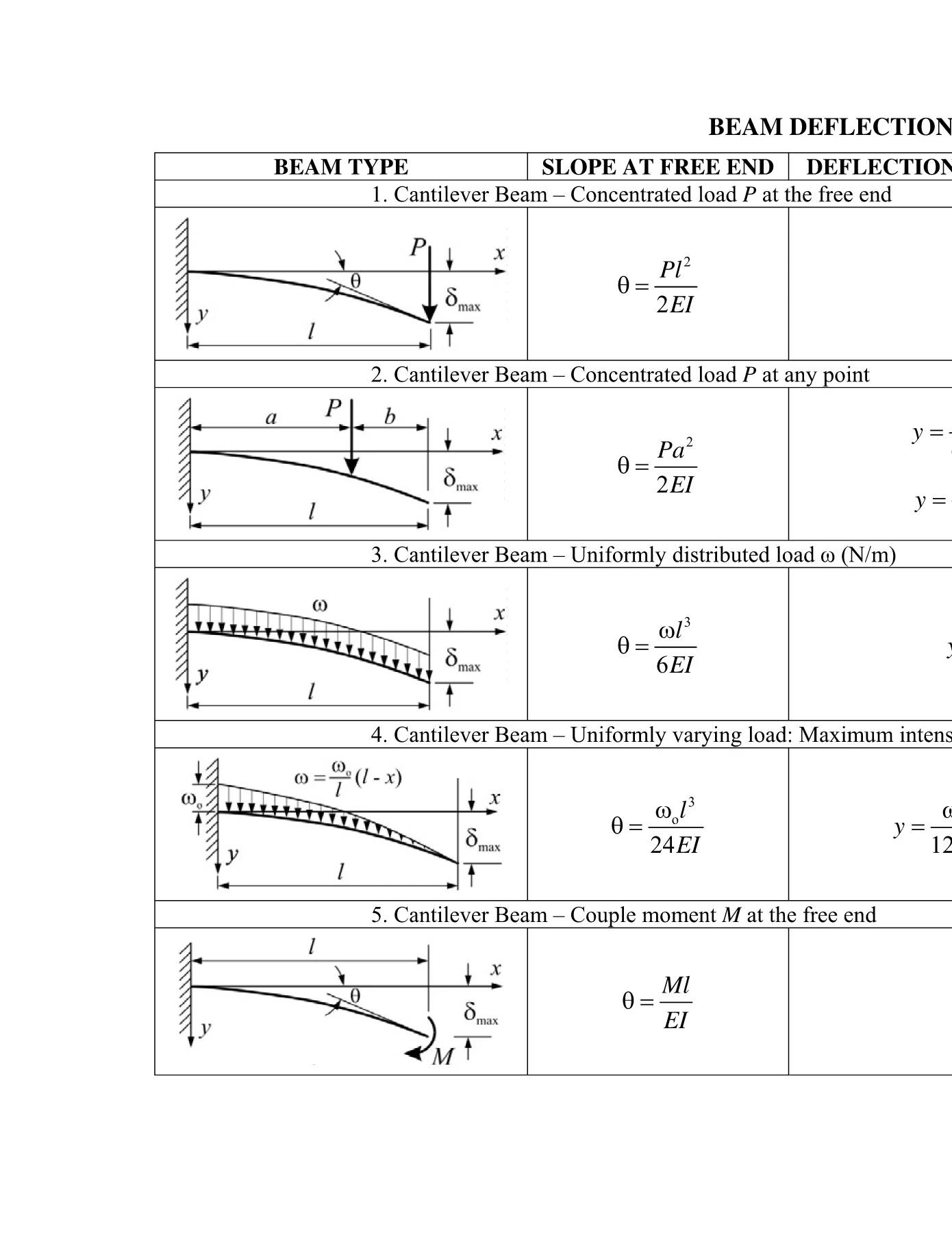
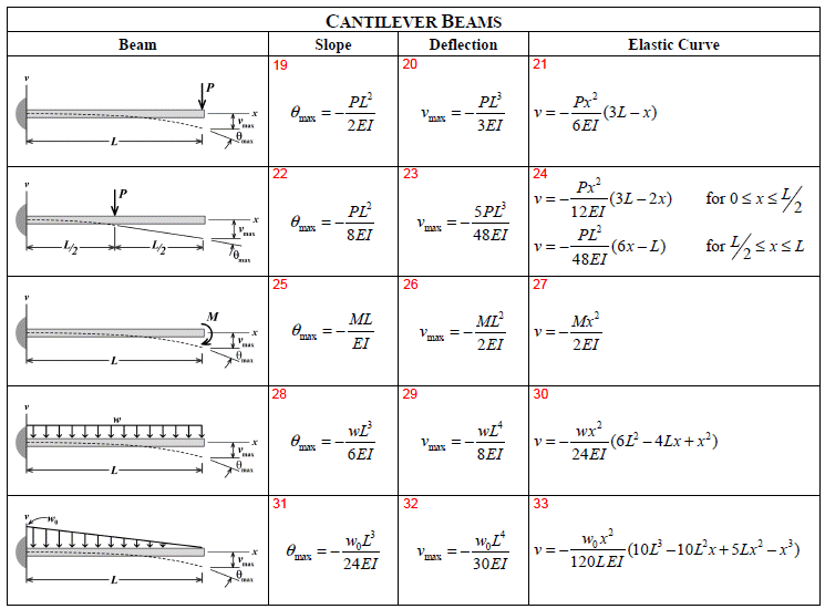
1. Point Load at the Free End
When a concentrated load P acts at the extreme tip of a cantilever with length L:
- Maximum Deflection (δmax):
(P × L³) / (3 × E × I) - Maximum Slope (θmax):
(P × L²) / (2 × E × I) - Maximum Moment (Mmax):
P × L(located at the fixed base)
2. Uniformly Distributed Load (UDL)
For beams subject to their own self-weight or continuous surface pressure represented by a constant load w (force per unit length):
- Maximum Deflection (δmax):
(w × L&sup4;) / (8 × E × I) - Maximum Slope (θmax):
(w × L³) / (6 × E × I) - Maximum Moment (Mmax):
(w × L²) / 2
3. Intermediate Concentrated Load
When a concentrated force P is placed at a distance a from the fixed wall (where a < L):
- Deflection at the load point:
(P × a³) / (3 × E × I) - Maximum Deflection at the tip:
[(P × a²) / (6 × E × I)] × (3L - a)
Beyond the load point, no bending moment exists, meaning the beam extends in a straight tangent line from the point of application to the free end.
4. Applied Moment at the Tip
If an external couple or rotational moment M is applied directly to the free end:
- Maximum Deflection (δmax):
(M × L²) / (2 × E × I) - Maximum Slope (θmax):
(M × L) / (E × I)
The Critical Role of Flexural Rigidity (EI)

In all deflection formulas, the denominator contains the product E × I, known as flexural rigidity. This combined term quantifies a beam's resistance to rotational bending.
Modulus of Elasticity (E)
The modulus of elasticity is an intrinsic material property measuring stiffness under axial stress. High-modulus materials undergo less elastic strain for a given stress level. Typical values include:
- Structural Steel: ~200 GPa (29,000 ksi)
- 6061-T6 Aluminum: ~69 GPa (10,000 ksi)
- Douglas Fir Timber: ~11–13 GPa (1,600–1,900 ksi)
- Carbon Fiber Composites: ~70–150+ GPa depending on lay-up
Area Moment of Inertia (I)
While material choice matters, geometric distribution of cross-sectional area relative to the neutral axis often exerts a far greater impact. For instance, the moment of inertia for a solid rectangular section of width b and depth h is:
I = (b × h³) / 12
Because height (depth) is cubed, doubling the depth of a cantilever reduces its deflection by a factor of eight. This cubic scaling explains why wide-flange I-beams and deep rectangular hollow sections are preferred over round solid bars for long cantilevered reaches.
Handling Complex Loading via Superposition
Real-world cantilevers rarely experience isolated, textbook loading conditions. A real exterior balcony experiences:
- The uniformly distributed dead weight of the concrete and steel framing.
- A distributed live load from foot traffic.
- A point load along the outer edge from a safety handrail system.
- Potential wind pressure acting upward or downward.
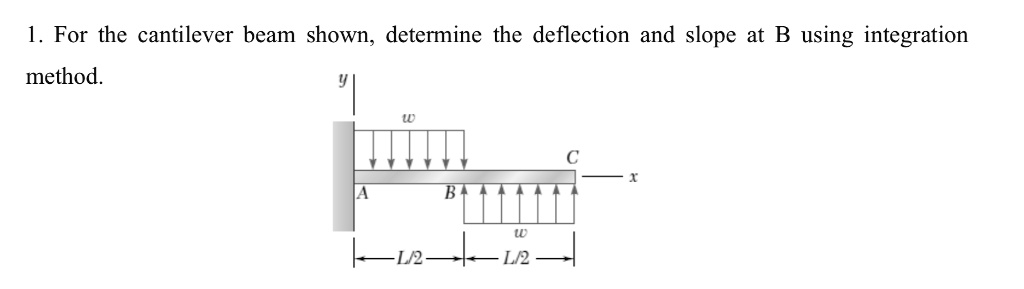
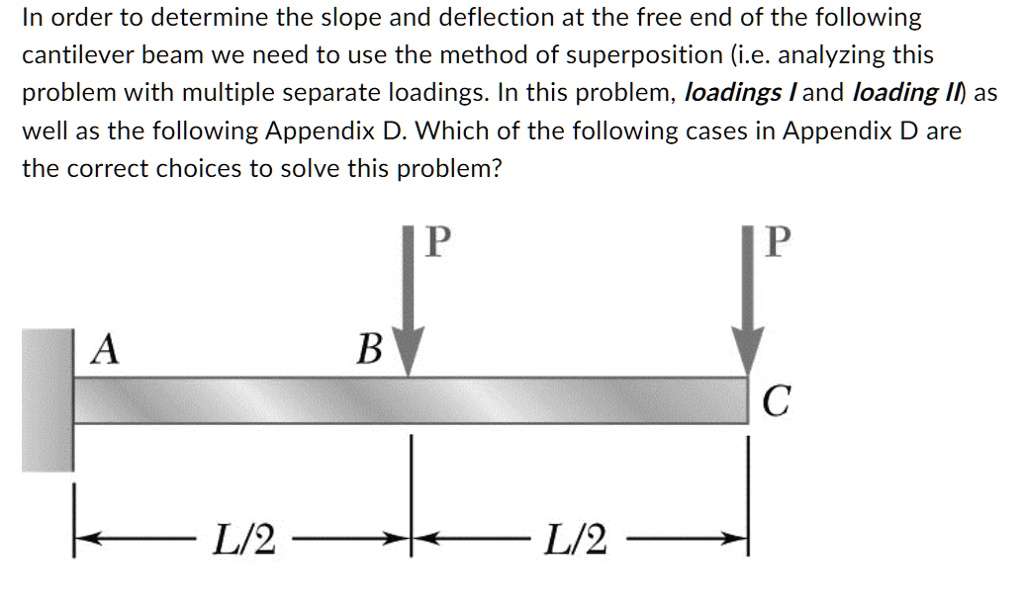
Because the governing differential equations of linear elasticity are linear, engineers apply the principle of superposition. This rule states that the total deflection at any coordinate x equals the sum of the individual deflections caused by each distinct load acting independently:
δtotal = δUDL + δPointLoad + δMoment
A capable online solver automates superposition instantaneously, removing the need to compute, track, and sum separate values by hand.
Serviceability Limits: How Much Deflection Is Acceptable?
Calculating deflection is only half the battle; structural engineers must compare the results against allowable deflection limits set by building codes and mechanical standards. Because cantilevers only have one fixed anchor, they feel more flexible than span-supported beams. Consequently, cantilever deflection criteria are strictly enforced.
Typical design limits include:
- Rovers, Bridges, and Heavy Equipment: Often limited to L / 300 or tighter to maintain mechanical alignment.
- General Building Overhangs (IBC/AISC): Commonly specified between L / 180 (for total load) and L / 240 or L / 360 where plaster or brittle glass facades are attached.
- Industrial Cantilever Shelving: Frequently allowed up to L / 100, provided the deflection does not cause storage containers to slide or bind.
When Do Standard Formulas Fail?
Before relying on simplified solver outputs, ensure your engineering scenario meets the baseline assumptions of classical beam theory:
- Small Deflections: Euler-Bernoulli formulas assume that deflections remain small relative to beam length (typically δ < L / 10). If a flexible polymer strip or long fishing rod bends into large curves, geometric nonlinearity takes over, requiring non-linear finite element analysis (FEA).
- Shear Deformation (Timoshenko Beams): For deep, short cantilevers (where length is less than roughly four times the cross-sectional depth), internal shear forces contribute noticeably to total tip displacement. Standard solvers ignoring shear slightly underestimate deflection on deep beams.
- Support Elasticity: Standard formulas assume a 100% rigid clamp at the wall. In physical fabrications, connection bolt stretch, baseplate bending, or concrete wall flexibility introduce rotational compliance, significantly increasing total tip deflection.
Conclusion
Whether you are rapidly sizing a structural channel or refining a machinery arm, understanding cantilever deflection formulas is foundational. Utilizing a modern calculation tool eliminates manual math errors, facilitates quick design iterations, and guarantees your structures remain both safe and within serviceability guidelines.