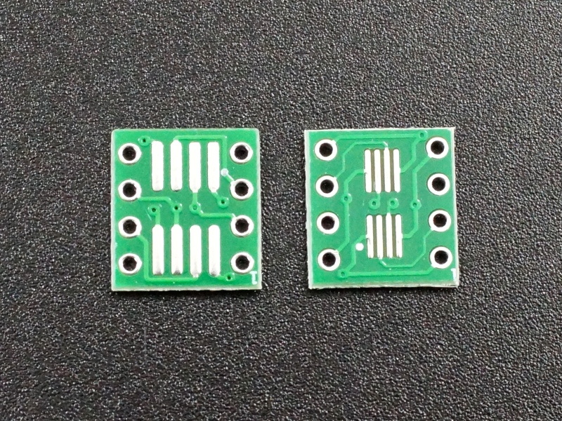
SMT to DIP Adapter Guide: Types, Uses, and Soldering
Surface-mount technology (SMT) has largely replaced through-hole components in modern commercial electronics due to its space-saving efficiency and suitability for automated manufacturing. However, when it comes to hobbyist prototyping, breadboard testing, or repairing older hardware, working with tiny microchips and transistors can be frustrating. This is where an SMT to DIP adapter becomes an indispensable tool on your workbench.

By converting fine-pitched surface-mount footprints into standard dual-in-line package (DIP) layouts, these adapters allow engineers, makers, and technicians to interface modern ICs with breadboards, perfboards, and through-hole sockets.
What is an SMT to DIP Adapter?
An SMT to DIP adapter is a specialized printed circuit board (PCB) designed to bridge the gap between two different packaging formats. On one side, it features copper pads matching a specific surface-mount footprint—such as SOIC, TSSOP, QFP, or QFN. On the other side, it breaks those connections out to standard 0.1-inch (2.54mm) spaced through-hole pins.
Typically, the adapter board comes bare, allowing you to solder your surface-mount chip directly onto the landing pads. You then solder standard header pins into the through-hole pads, transforming your microscopic chip into something you can easily plug into a solderless breadboard or a DIP IC socket.
Common Types of SMT to DIP Adapters
Because surface-mount components come in a massive variety of shapes and pin counts, adapters are manufactured to match specific package types. Before purchasing or making one, you must identify your IC's exact package style and dimensions.
SOIC to DIP Adapters
Small Outline Integrated Circuit (SOIC) packages are among the easiest SMT components to adapt. They feature gull-wing leads on two opposing sides with a standard 1.27mm pin pitch. An SOIC-8 to DIP-8 adapter is perhaps the most common variant, widely used for operational amplifiers, EEPROMs, and small microcontrollers.
TSSOP and SSOP Adapters
Video: SOIC to DIP Adapter for breadboarding

Thin Shrink Small Outline Package (TSSOP) and Shrink Small Outline Package (SSOP) components have a tighter pin pitch, usually 0.65mm or 0.5mm. Adapters for these components require a steady hand and careful soldering techniques, as the pads are much closer together and prone to bridging.
QFP and QFN Adapters
Quad Flat Package (QFP) and Quad Flat No-leads (QFN) chips have pins or pads on all four sides. Adapters for these parts often look like breakout boards with a central square footprint and two rows of header pins running down the sides. QFN packages, which lack traditional protruding leads, require bottom-pad soldering, making them the most challenging to adapt manually.
How to Use an SMT to DIP Adapter Effectively
Successfully mounting a tiny surface-mount chip onto an adapter board requires proper tools, good lighting, and patience. Follow these steps to ensure a reliable connection.
- Verify the Footprint Match: Double-check the datasheet of your IC. Confirm not just the package name (e.g., SOIC-16), but also the body width and pin pitch. A mismatch will result in bent pins or unaligned pads.
- Clean the Board: Wipe down the adapter PCB with isopropyl alcohol to remove any oils or manufacturing residue that might prevent solder from adhering properly.
- Tack the IC in Place: Apply a tiny amount of flux to the pads. Place the IC on the adapter, ensuring pin 1 on the chip aligns with pin 1 marked on the silk screen. Hold the chip steady and tack down one corner pin with your soldering iron. Check alignment visually under a magnifying glass or microscope before proceeding.
- Solder the Remaining Pins: Solder the diagonally opposite pin to secure the chip further. Then, proceed to solder the rest of the pins. Don't worry too much about minor solder bridges at this stage; they are easily fixed.
- Clean Up Solder Bridges: If adjacent pins accidentally bridge together with solder, apply fresh flux to the area and use clean solder wick (desoldering braid) with your iron to draw away the excess metal.
- Attach Header Pins: Insert break-away male header pins into the through-hole pads on the bottom of the board. Solder them securely from the top side, or flip the assembly over if the design permits.
Benefits of Using Adapters in Prototyping
Integrating these converter boards into your electronics workflow offers several distinct advantages:
- Cost Savings: Many modern integrated circuits are only manufactured in SMT formats. Adapters let you test them without investing in custom PCB production runs immediately.
- Reusability: Once soldered and tested, components on DIP headers can often be unsoldered or reused in final hardware builds.
- Easier Troubleshooting: Probing pins on a 0.1-inch header is vastly easier and safer than trying to touch multimeter probes to microscopic surface-mount legs without causing a short circuit.
Conclusion
Whether you are designing a custom circuit, testing a new sensor, or salvaging components from a broken device, an SMT to DIP adapter is an essential bridge between modern surface-mount technology and classic through-hole prototyping. By matching the right adapter to your component and using proper soldering and flux techniques, you can easily incorporate virtually any modern IC into your breadboard projects.